Check valves: product range
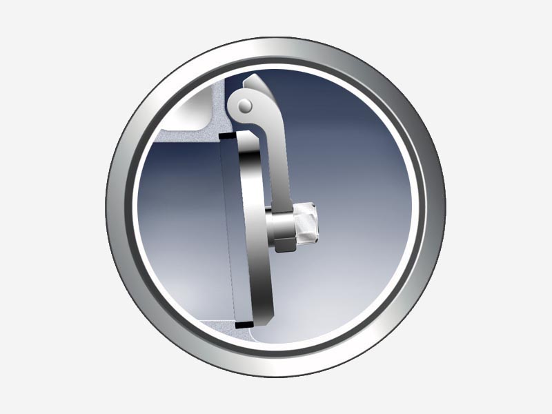
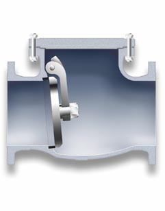
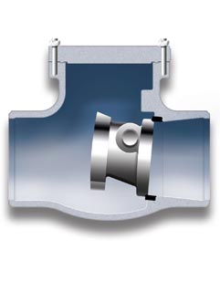
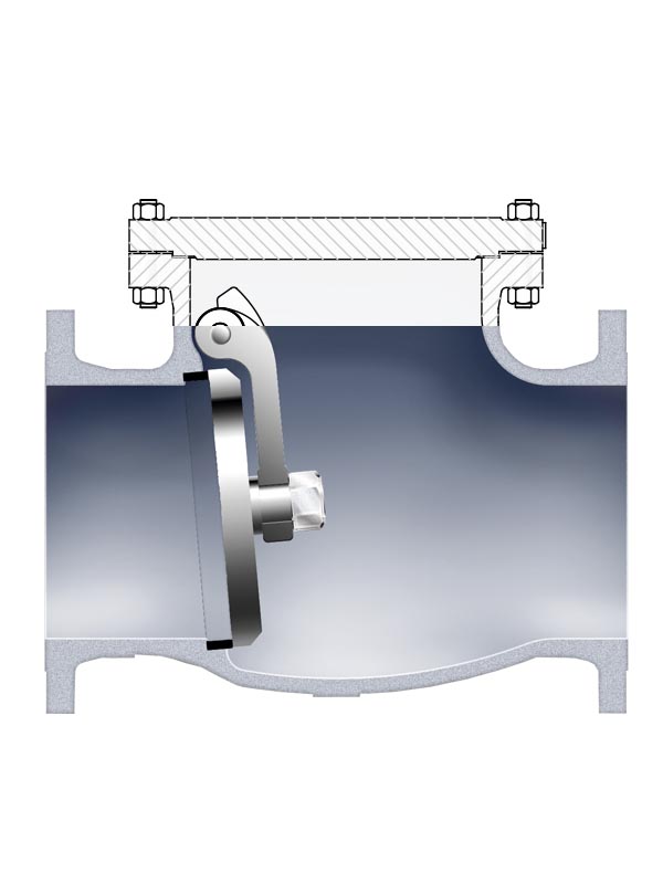
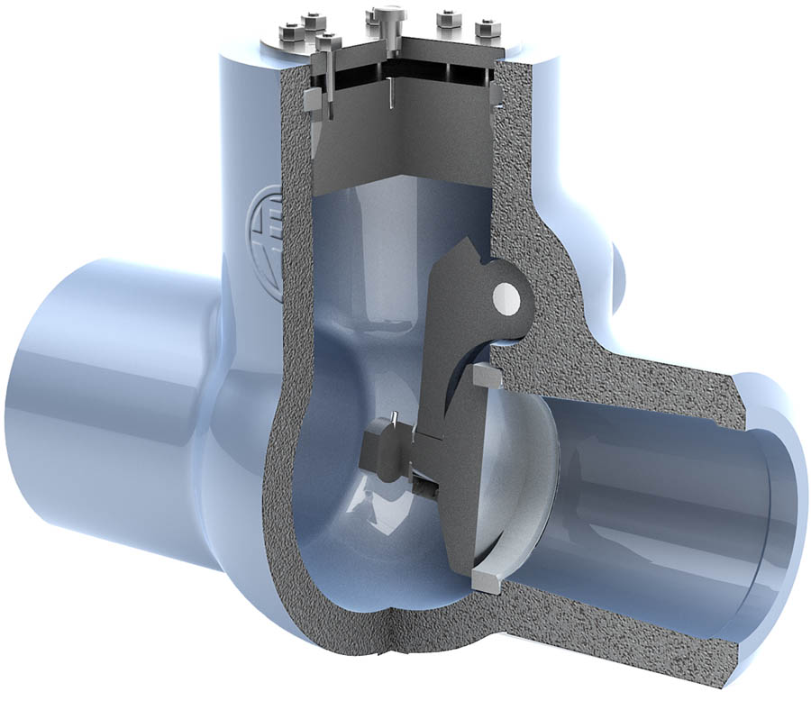
Swing Check Valves
Babcock swing check valve has a robust and reliable design to withstand severe shocks during service and provide a low head loss. The disc design prevents disc rotation normally induced by the flow, and it is securely fastened to the hinge. A precise machining will avoid jamming at the seating areas.
Code 42
Type: Swing Check
Cover: Bolted
Sizes: 1/2″- 48″
ANSI Class: 150-2500
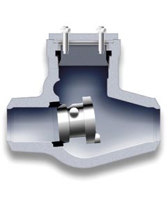
Code 45
Type: Swing Check
Cover: Pressure Seal
Sizes: 2″- 24″
ANSI Class: 600-4500
BLOWING DEVICES
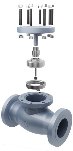
Babcock Valves’ Swing Check Valves can be transformed onto line blind valves or hydrotest valves by adapting our Blowing device, that fits perfectly on our valves after replacing the hinge pin, the hinge arm and the disc.
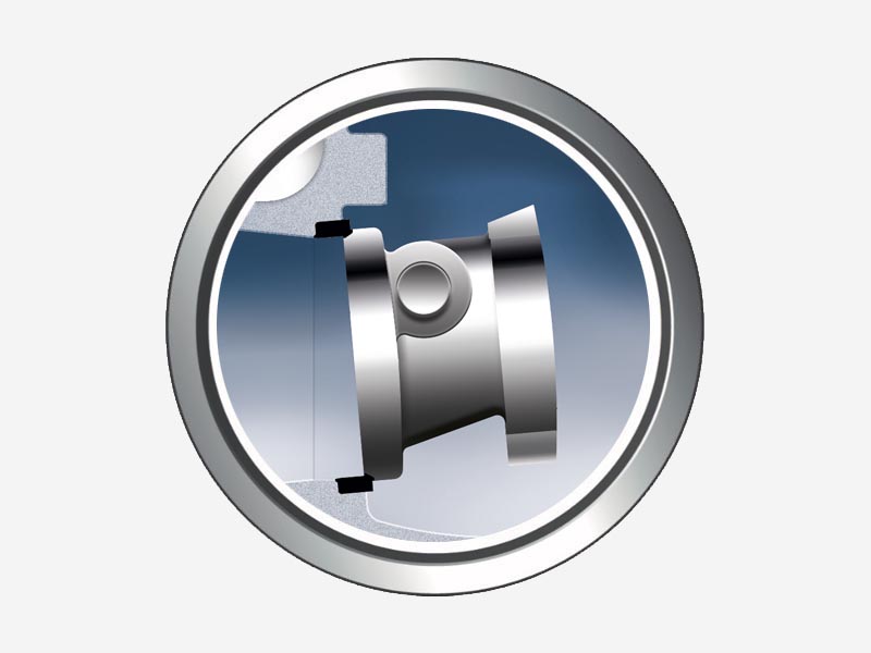
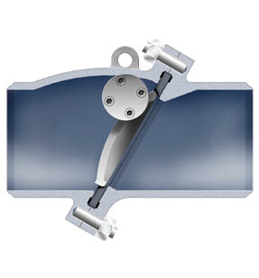
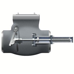
Tilting Disc Check Valves
Design for high flow speed getting a quick and control closing. Our especially designed shape of the disc and seat guarantee that the disc will be in contact with the seat before the reverse flow velocity has reached its maximum value. The conical design of both sealing parts helps absorbing the disc impacts better than with straight type discs, as frequently occurs with other designs of check valves.
Code 02
Type: Tilting Disc
Cover: Bolted
Sizes: 2″- 48″
ANSI Class: 150-900
Code 05
Type: Tilting Disc
Cover: Pressure Seal
Sizes: 2″- 48″
ANSI Class: 600-4500
Code 48
Type: Split Body Tilting Disc
Sizes: 6″- 28″
ANSI Class: 150-600
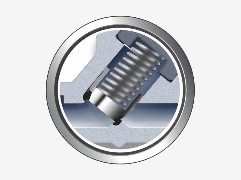
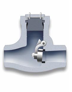
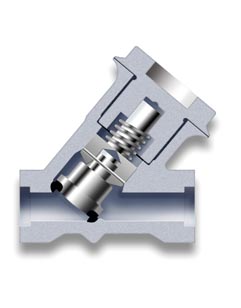
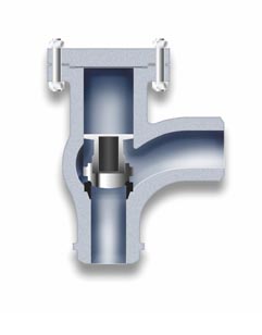
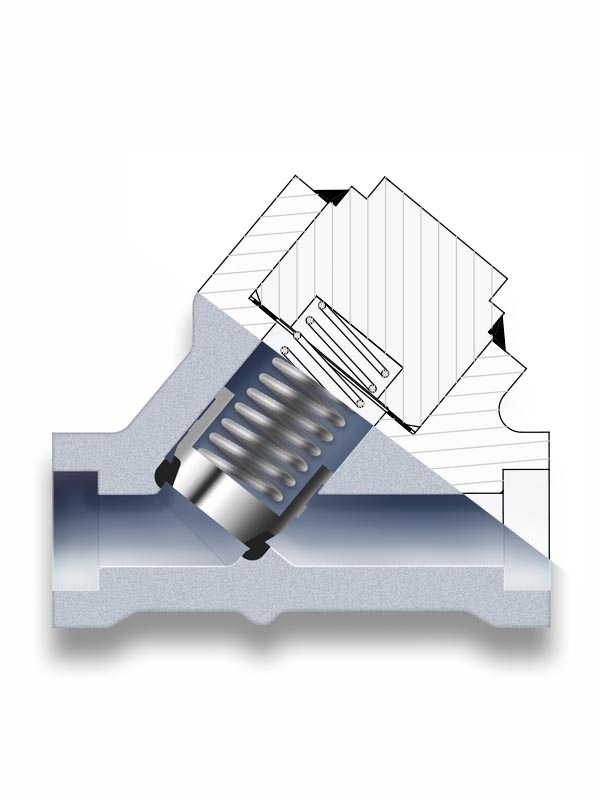
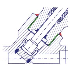
Piston Check Valves
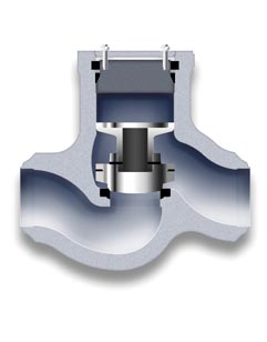
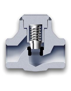
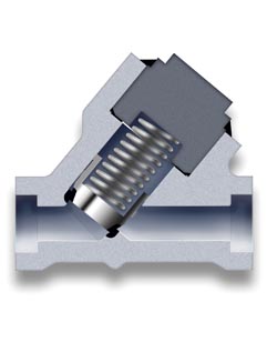
With the flow under the disc, the inlet line pressure forces the disc to move within the body bore, allowing the fluid flow through the valve. In case of quick reverse flow, the disc will automatically return to close position. Our piston check valves are available in straight body design, “Y” pattern and “Y” angle pattern, with or without disc spring.
Code 04
Type: Horizontal Lift Check
Cover: Pressure Seal
Sizes: 2″- 48″
ANSI Class: 600-4500
Code 09
Type: Horizontal Lift Check
Cover: Threaded & Welded
Sizes: 1/2″- 3″
ANSI Class: 150-4500
Code 51
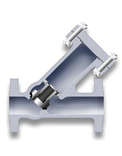
Type: Y-Piston Check
Cover: Threaded & Welded
Sizes: 1/2″- 3″
ANSI Class: 150-4500
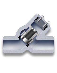
Code 52
Type: Y-Lift Check
Cover: Bolted
Sizes: 1/2″- 24″
ANSI Class: 150-2500
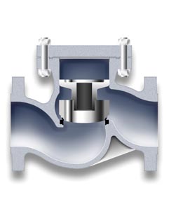
Code 07
Type: Horizontal Lift Check
Cover: Bolted
Sizes: 1/2″- 24″
ANSI Class: 150-900
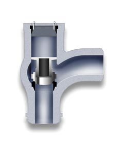
Code 06
Type: Angle Lift Check
Cover: Pressure Seal
Sizes: 2″- 24″
ANSI Class: 600-4500
Code 55
Type: Y-Lift Check
Cover: Pressure Seal
Sizes: 2″- 24″
ANSI Class: 600-4500
Code 54
Type: Y-Piston Check Zero Leakage
Cover: Threaded & Welded
Sizes: 1/2″- 3″
ANSI Class: 150-4500
Code 01
Type: Angle Lift Check
Cover: Bolted
Sizes: 2″- 48″
ANSI Class: 150-900
Other Check Valves
QUICK CLOSING
A swing type check valve especially designed for protection of the steam turbine systems.
Code 42P / 45P
Type: Steam Extraction Quick Closing Non Return
Cover: Bolted / Pressure Seal
Sizes: 3″-64″
ANSI Class: 150-2500
DUAL PLATE
A compact design which permits an immediate response regardless of flow characteristics, by means of retainerless two semi discs.
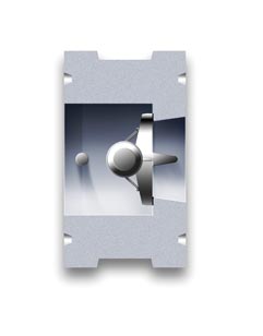
Code 43
Type: Dual Plate Wafer Check
Sizes: 2″- 48″
ANSI Class: 150-600
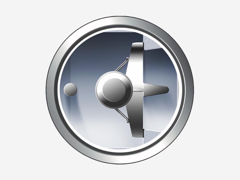
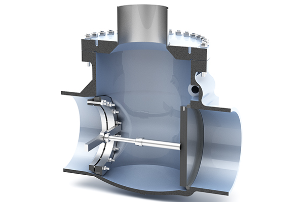
AXIAL FLOW
The streamlined design of the axial flow check valve permits its fully opening at low flows and fluid velocities, getting a low pressure drop.
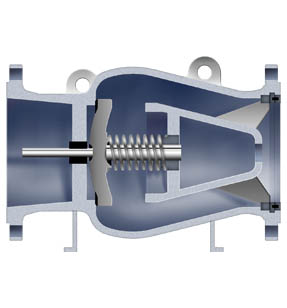
Code 49
Type: Axial Flow Check
Sizes: 6″-44″
ANSI Class: 150-600
SPLIT BODY
The split body tilting disc check valve design consists in two bodies diagonally bolted which provide a non-slam closing and a reduced head loss.
Code 48
Type: Split Body Tilting Disc
Sizes: 6″- 28″
ANSI Class: 150-600
Types of Cover
The most common connection between valve body and cover for ASME ratings up to 600.
Under demand, it can be also used for high pressure applications up to class 2500.
The Babcock’s strong designs and a precision machining of bodies and coverss shall guarantee the best performances of the valves during operation.
The right sealing between body and cover is made by designing a more than sufficient type and number of bolts, and selecting the best gasket for each service.
There are different joint / gasket designs for each applicable ASME rating. A flat oval gasket is normally used for low pressure (class 150) and a spiral wound gasket for intermediate pressures (class 300) and high pressure (class 600). Other type of joints as corrugated or ring type are also available under demand.
NOTE:
For Class 900 and superior, the Bolted Cover gasket used is RTJ.
STANDARD BOLTED COVER GASKETS
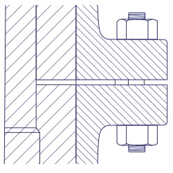
Class 150
Detail for
FLAT GASKET
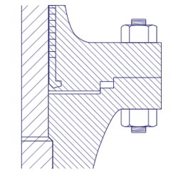
Class 300
Detail for
FLAT GASKET
Class 600
Detail for
FLAT GASKET
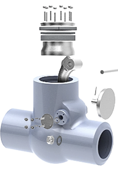
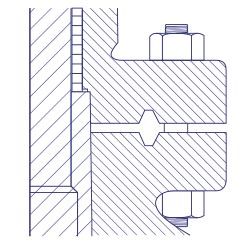
Pressure seal cover allow high pressure service, typically in excess of 15 Mps (2250 psi).
The main feature about the pressure seal cover is that the body-cover joints seals improves as the internal pressure in the valve increases, compa- red to other constructions where the increase in internal pressure tends to create leaks in the body-cover joint.
The basic operation of this kind of valve, where the seal is achieved from the pressure exerted by the fluid flowing trough the valve, is as follows:
Internal pressure forces the cover upwards against the gasket, creating forces in the contact areas between the gasket and the cover and between the gasket and the body.
Leaks most commonly arise at the contact surface between the gasket and the body. The area where the body is in contact with the joint is covered by stainless steel, improving surface’s quality and avoiding corrosion issues.
Gaskets are carefully designed to produce a tight seal regardless of the line conditions, that can be easily dismantled for maintenance operations.
GENERAL DESCRIPTION
The basic operation of this kind of valve, where the seal is achieved from the pressure exerted by the fluid flowing through the valve, is as follows:
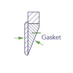
Fig. 1
Forces making the seal
Internal pressure forces the cover upwards against the gasket creating forces in the areas of contact between the gasket and the cover (disc shaped area). and between the gasket and the body (valve passage area). See (Fig. 1 ). The quality of the seal between the surfaces depends upon two basic considerations, these being the surface quality of the areas in contact, and the degree of force (load per unit area) which holds them together.
It is easier to achieve the seal from the two gasket surfaces where a seal is made (gasket-cover and gasket-body) in the gasket cover contact area, in comparison to the larger component of the force exerted by the pressure inside, and it is more than sufficient to provide a tight seal.
Leaks most commonly arise at the contact surface between the gasket and the body. The area where the body is in contact with the joint (Fig. 2) is covered with stainless steel, and this improves surface quality and avoids corrosion problems. The force actuating between the contact joint body surfaces is the horizontal component of force perpendicular to the contact surfaces between the bevelled surfaces of the joint and cover.
The efficiency of the seal between the gasket and body is determined basically by the gasket angle, which in turn determines the horizontal force component that will act upon them. The smaller the gasket angle, the greater the horizontal component is, and hence, the harper the angle on the bevelled surface, the greater the horizontal component, and the better the seal.
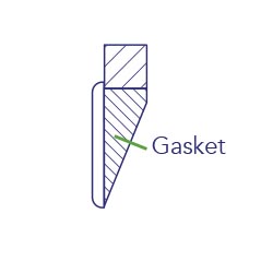
Fig 2
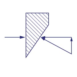
Fig. 3
Angle 25º
A gasket designed with a 25° angle (Fig. 3) will turn into radial force, a greater component of the force exerted by the pressure from the line on the cover, than a gasket designed with an angle of 30° 45° (Fig.4). Moreover, in order to achieve large unitary loads, the surface upon which the force is exerted may be reduced, with checks being performed to ensure that the surface is sufficient to support the load without cracking.
When a pressure seal joint is required to seal over a large range of pressures, there may be difficulties. A gasket which is sufficiently small so as to seal under a pressure of 500 psi. may not support 2.500 psi.
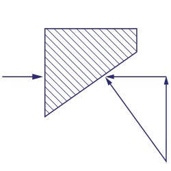
Fig. 4
Angle 45º
A way to overcome this problem is to design the gasket cover contact surfaces to have a difference of one degree between them (Fig. 5).
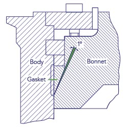
Fig. 5
Before the gasket is tightened, only its edge is in contact with the cover (Fig. 6).
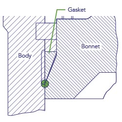
Fig. 6
Under pressure, one part of the gasket will deform and enter into contact with the cover (Fig. 7).
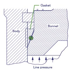
Fig. 7
A careful design of the gasket pressure seal angle will prevent those more serious difficulties found with large angle gaskets (30°-45°). With a narrow gasket angle (25°), a tight seal can be achieved by applying little pressure, and once the seal has been made, it will stay tight regardless of line conditions. Certain tests performed with narrower gaskets (15°-20°), showed that the seal became so tight that it was impossible to remove the gasket. A gasket of approximately 25° is found to produce a seal that can be easily dismantled.
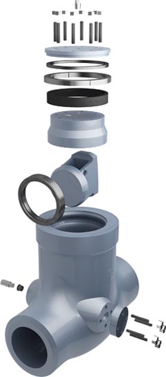
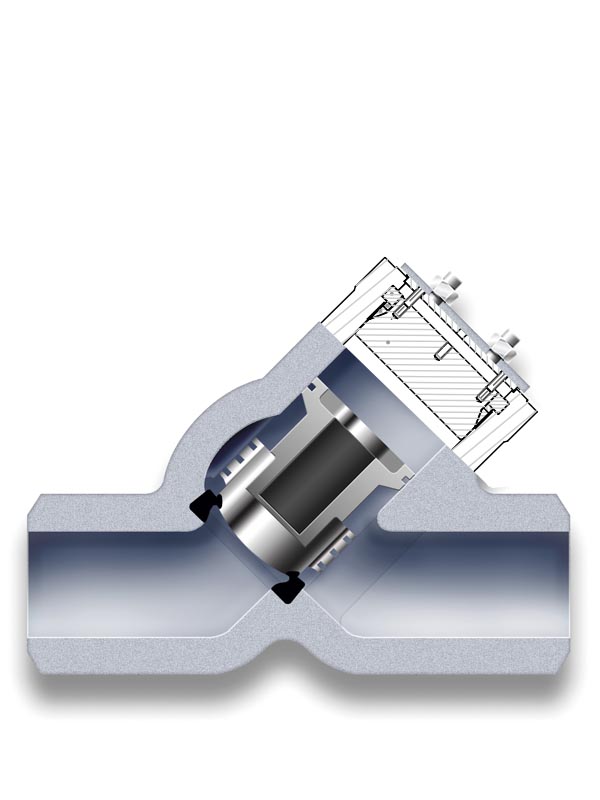
BODY
Available both in cast and forged steel, it has been designed to meet all therequirements of ASME, API and British Standards.
The body-bonnet connection is made by a pressure seal gasket. Its prestress condition is achieved by meansof bolts screwed to the bonnet flange. Ends are normally butt-welding although they can be also flanged on request.
All bodies are provided with integrally cast bosses, located and sized in accordance with ASME B16.34, which allow the provision of drain.
COVER
Usually constructed in the same materials as the body.
SEAT RING
Supplied in forged stainless steel, hardfaced with Stellite-6 (2mm of min. thickness). Seat ring is renewable, normally welded to the body. Sealing contact surface is lapped fora perfect tight seal.
DISC
The disc is normally constructed in forged stainless steel for diamters upto 8”, and in cast steel of the same material as the body for larger sizes. Contact face is overlayed with 2 mm minimum thickness of Stellite-6.
It is designed so that the valve can operate both in horizontal and vertical positions.
PRESSURE SEAL GASKET
The pressure seal gasket is usually supplied of compressed graphite,bordered on the upper and lower edges with braided filaments of carbon fiber.
Gasket can also be made in stainless steel.
HINGE (ARM)
The arm is constructed of the same material as the valve body. Designed to swing smoothly, is provided with an integral mechanical stop, suitably machined, which contacts the valve body when the valve is in fully open condition, and avoids the disc to create the first contact.
HINGE PIN (SHAFT)
Constructed from a stainless steel forged bar, is normally designed for being assembled externally through the side/s of the valve body, although internal shaft designs are also available on request.
In the normal external shaft construction, one or two cover/s (19A), fitted to the body with 4 studs (28A) assure a perfect tightness. Seal between cover/s and body is achieved by using spiral wound gaskets (17A).
For some special applications, to avoidslamming effect, shock absorbers (dashpots) are installed in the valve, connected to the hinge pin throughstuffing box/es.
SPACER RING
Made of a single piece covering the upper part of the pressure seal gasket. It is normally manufactured in the same material as the body.
GASKET RETAINER
It is made normally of the same material as the body, and constructed in four pieces, called segments. The segments are sized to minimize the gap between them.
The segmental ring supports all the forcers transmitted from the bonnet through the pressure seal gasket and the spacer ring. It is calculated to withstand all the force withoutcrac- king.
COVER RETAINER
Designed sufficiently resistant to withstand the forces transmitted by the cover stud (28).
The cover retainer is normally made of the same material as the body, but it can be constructed in any other material on request. It is machined tomach exactly with the body, what guarantees a perfect alignment of the unit.
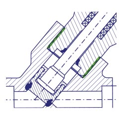
The double sealed design.
Unlike the bolted cover and pressure seal body-cover closure systems, the threaded & welded system consists of a double-sealed design, first by threading the cover-yoke to the body, and second by sealing it by means of a welding seam.
The necessary non destructive tests are carried out to ensure a perfect sealing.
Under demand, a sealing gasket can also be placed between body and cover.
The threaded & welded design is primarily used on small size forged valves up to 2″, and for high pressure ratings, from ASME class 900 to 4500.
Threaded
Welded
BABCOCK VALVES S.A.
ADDRESS
P.E. Abra Industrial, Parcela 1.5.6 – 48530 Ortuella (Bizkaia) Spain
TELEPHONE
(+34) 944 536 423
FAX
(+34) 944 535 739
Inquiry form
You can send us any question of your interest.
We will get back to you as soon as possible.
Legal disclosures
Cookies policy
Privacy statement