Babcock's Special Valves
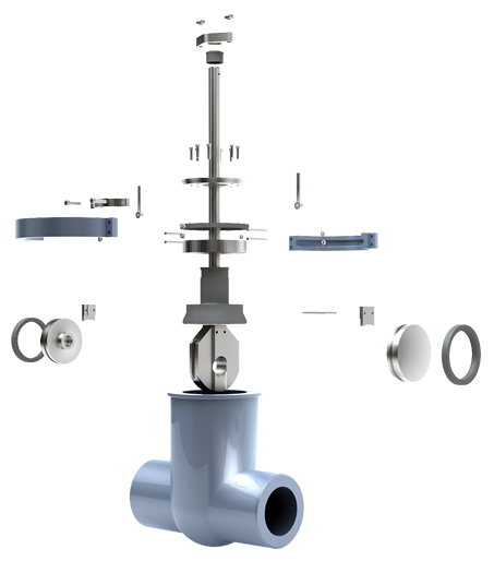
Reliability with low operating forces.
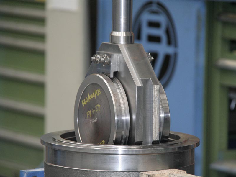
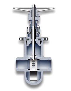
An alternative to double disc valves, having two discs but only one wedge instead of two. The discs are in permanent contact with the seat rings, getting a tight seal due to the horizontal inconel spring located in between and without the wedging system help.
The parallel slide gate valve is an alternative to double disc valves, having two discs but only one wedge instead of two. The discs are in permanent contact with the seat rings, getting a tight seal due to the horizontal inconel spring located in between and without the wedging system help.
The complete guiding system is precisely machined for ensuring a smooth open and close operations and eliminating vibrations.
The parallel slide gate valve is recommended to be used for clean fluids and steam applications and for medium or high pressure service.
A wide range of construction materials, actuation systems and accessories are available for each case.
PRODUCT RANGE
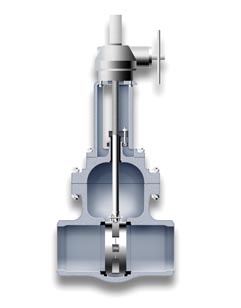
Code 87
Type: Parallel Slide
Bonnet: Bolted
Sizes: 2″ – 48″
ANSI Class: 150-900
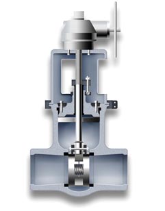
Code 89
Type: Parallel Slide
Bonnet: Pressure Seal
Sizes: 2″ – 48″
ANSI Class: 600-4500
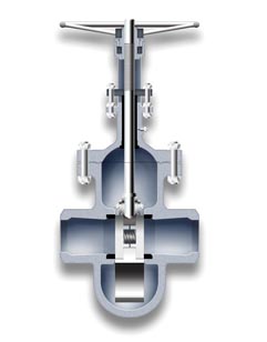
Code 88
Type: Parallel Slide (with follower eye)
Bonnet: Bolted
Sizes: 2″ – 48″
ANSI Class: 150-900
Code 86
Type: Parallel Slide (with follower eye)
Bonnet: Pressure Seal
Sizes: 2″ – 48″
ANSI Class: 600-4500
PARALLEL SLIDE DESIGN MAIN FEATURES
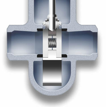
CODE 86-88
Follower eye for very laminar flow is available on request. It avoids any turbulences and minimizes the pressure drop.
-
Two discs and just one wedge design gate valve.
-
Parallel slide gate valve provides a smooth flow path between seats.
-
This design of gate valve is commonly used for clean fluids and steam applications.
-
System pressure is used to provide isolation. The closing is only made over one of the seats. The higher pressure in the system, the better closing tightness.
-
The discs have a certain movement to assure its right alignment with the seats contact faces when closing (seal is established on outlet seat face only), avoiding any mechanical stress.
-
The inconel spring located between both discs, provides initial seating force. Once the discs are in the right position, no additional torque is necessary to achieve a positive seal.
-
Torque requirement is lower than other gate valves as wedge type because needs lower operative forces.
-
The wiping action of the discs over seats while the valve is operating removes debris and prevents premature wear of the components. A long life service is guaranteed by means of hardening seats and discs with an extra hard material as Stellite 6, Tribaloy or others.
-
Parallel slide system avoids jamming related to cooling down of the pipeline.
-
A wide range of construction materials, actuation systems and accessories are available for each case.
The most reliable shut-off valve.
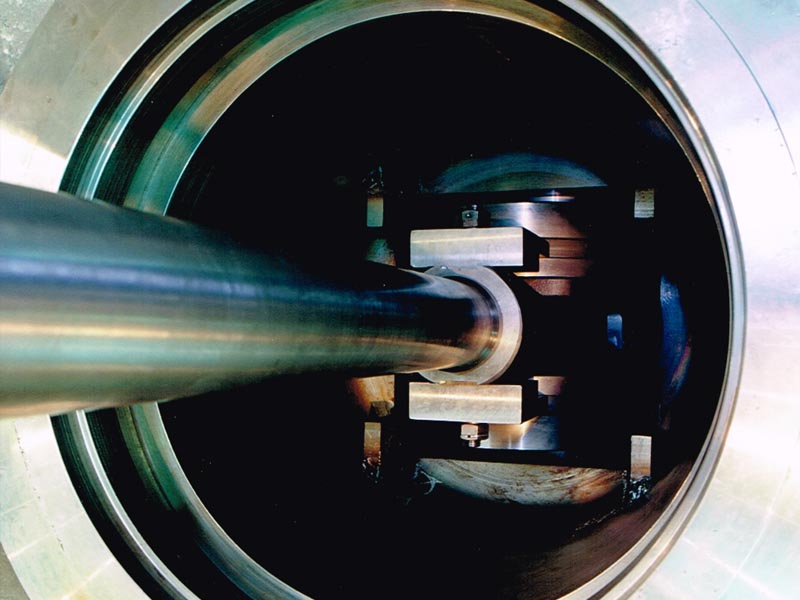
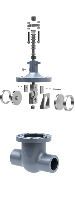
The so called double disc valve incorporates a double disc, wedge and seat system which makes this design unique, being designed to assure a reliable operation under the most severe service conditions.
.
The two independent trunnion mounted discs which permit each disc to rotate a few degrees during closing. This rotating feature allows the discs to seat in a different position on each closing stroke which provides even wear and prevents small imperfec- tions from growing into major leaks.
The double wedging assembly is designed to impart the stem thrust to each disc which provides bi-directional sealing at low or zero differential pressures. As the differential pressu- re across the valve increases, the seating load on the downstream disc increases to provide high differential pressure sealing while the upstream disc moves away from the upstream seat; and allows the valve to be used in applications with large thermal transients.
This valve is commonly used for isolation of boiler water main feed lines. It is also very useful for cryogenic applications, when the effect of the differential thermal contraction may require an extra thrust to close the valve properly (zero-leakage).
A wide range of construction materials, actuation systems and accessories are available for each case.
Design: ASME B16.34, API 600, BS 1414. Testing: ASME B16.34, API 598, BS EN 12266-2.
PRODUCT RANGE
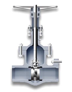
Code 82
Type: Double Disc
Bonnet: Bolted
Sizes: 2″ – 72″
ANSI Class: 150-900
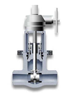
Code 85
Type: Double Disc
Bonnet: Pressure Seal
Sizes: 2″ – 48″
ANSI Class: 600-4500
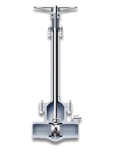
Code 83
Type: Double Disc Cryogenic
Bonnet: Bolted
Sizes: 2″ – 48″
ANSI Class: 150-900
TECHNICAL ADVANTAGES OF THE DOUBLE DISC WEDGE ASSEMBLY
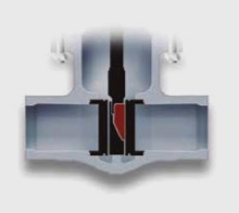
Reliable operation
The double disc gate valve has been designed to assure reliable operation under the most severe service condi- tions. Due to the special configuration and geometry of the upper wedge inclined face, any possibility of locking the disc in closed position is eliminated, even when closed quickly or subjected to severe thermal transients.
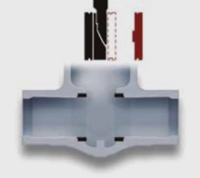
Easy maintenance
The four piece double disc wedge assembly can neither be incorrectly assembled nor become disengaged while in service. No special fitting at site is required for maintenance. The repair of minor seat or disc damage is greatly simplified because the seats and discs can be lapped independently of each other. Disassembly and maintenance can be accomplished without special tools or elaborate rigging.
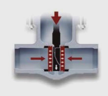
Low pressure sealing
The wedge assembly is designed to impart sufficient thrust to each disc to maintain low pressure sealing. As the differential pressure across the disc increases, the seating load also increases, thus providing a tight seal throughout the entire range of operating differential pressures. Since the discs are independent of each other and the design is symmetrical, positive sealing can be maintained in either direction.
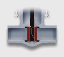
Uniform seat wear
The incorporation of a unique revolving disc feature assures maximum seat life. The two independent discs, during each closing stroke and immediately prior to the disc seating, rotate a few degrees in the plane of the seats. This rotating action forces the disc to seat in a different position on each stroke, equalizing wear on the seats and the discs. This movement of the discs creates a lapping effect whenever the valve is operated, removing particles from the sealing surfaces before they can become wedged between the seats and the disc and cause damage.
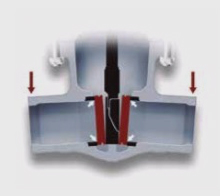
Uniform distribution of sealing pressure
The tight seal is guaranteed even when the valve seats have become out of parallel due to body distortion, due to the uniform distribution of the sealing pressures allowed by the exclusive wedge design.
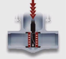
Uniform distribution of sealing pressure
Babcock’s double disc wedge system permits rapid closure without seat distortion. Internal moving parts decelerate independently of each other with the result that inertial forces are dissipated in a series of impacts over a period of time. The largest force is transmitted directly to the bottom of the valve body on a non-sealing surface. Forces transmi- tted directly to the seats a small percentage of the seats are a small per centage of the total inertial forces. This is a distinct advantage over valve designs in which the total inertial force is absorbed directly by the seating surface.
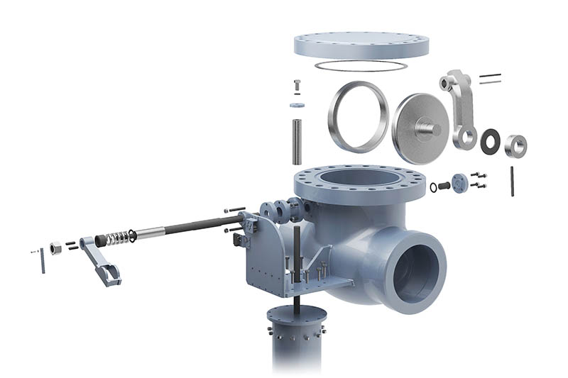
Designed for turbine protection in steam extraction lines.
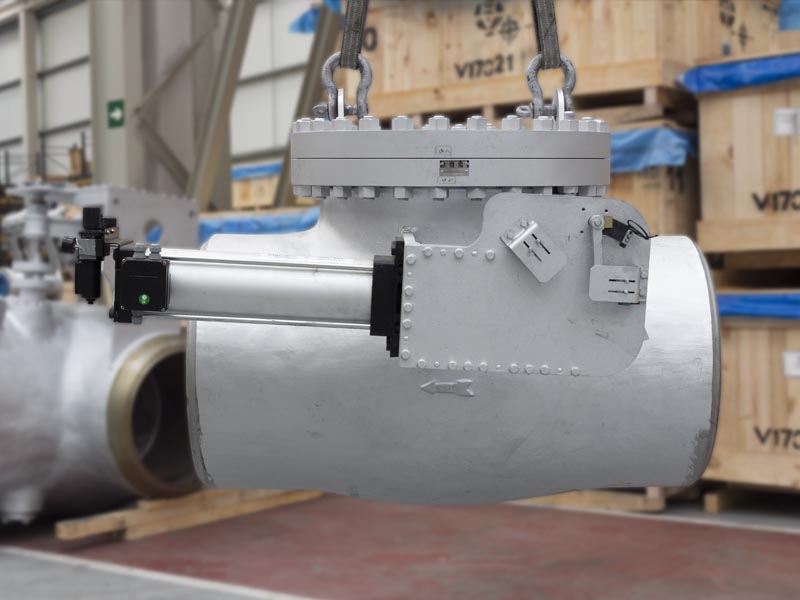
Babcock ́s QCNRV is a swing type check valve especially designed for protection of the steam turbine systems.
During normal operation of the installation, the valve works as a check valve with free swinging disc, to allow the steam extraction from the system without restrictions.
The valve also has a closing aid device by means of a pneumatic actuator, which shall immediately respond when a trip occurs. The valve shall close in a very short period of time to prevent the backflow of steam which might damage the turbine..
PNEUMATIC ACTUATOR
The pneumatic actuator is single-acting type. The weatherproof cylinder includes a spring which is compressed by an external air supply, permitting the valve acting as a normal swing check unit.
When there is a fail in the air supply or in the electrical supply, the spring shall be decompressed causing the immediate closing of the valve and preventing the backflow.
High reliability adjacent devices:
- Solenoid valve
- Two limit switches for open/close position
- Position transmitters 4-20mA
- Air set (min. IP65 protection class), including filter, regulator and manometer.
QCNRV video
Visit this page to see how one of our Quick Closing Non Return Valves works
PRODUCT RANGE
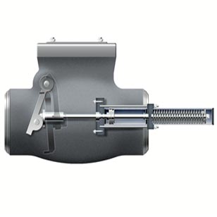
Code 42 / 45
Type: Steam Extraction Quick Closing Non Return
Cover: Bolted / Pressure Seal
Sizes: Up to 64″
ANSI Class: 150-2500
SHAFT CONFIGURATIONS
Single Shaft
A single shaft is engaged with the hinge by means of two keys. The friction with the packing does not avoid the shaft-hinge-disc assembly to swing freely and the position of the disc can be observed from the outside in the complete angular stroke.
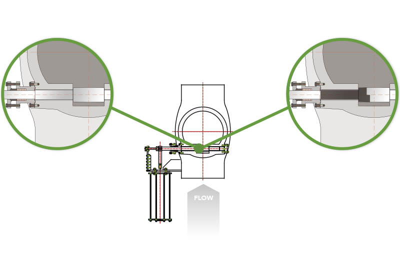
Double Shaft
With this design the disc-hinge assembly is not connected to the shaft by keys, and it is free to swing with independence of the shaft rotation.
A mating part to the hinge called clutch is attached to the shaft by keys and connects the cylinder in a “lost motion system”.
OPERATION PHILOSOPHY
Valve opens due to the inlet pressure
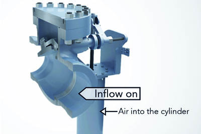
Normal operation
The steam extraction valve is a high performance swing check type valve which opens with inlet flow and closes automatically under no flow/pressure conditions, avoiding back flow from downstream.
The check valve is fitted with an auxiliary spring return single-acting pneumatic actuator controlled by a solenoid valve, which is energized to permit the air enters into the cylinder compressing the spring. The disc movement is released working freely during normal service.
Pump stops and disc returns to the close position
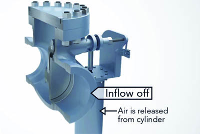
Turbine trip
In the event of a turbine trip or pump stop, solenoid is de-energized releasing the spring and consequently the air from the cylinder, provoking the immediate action on the lever arm and valve shaft which drives the disc to the close position.
The force generated by the spring will help to overcome the friction caused by moving parts.
The actuator is designed to close the valve in less than one second when flow stops, and to operate smoothly during at least 500 turbine trips.
Actuator is rearmed to permit the free swinging of the disc
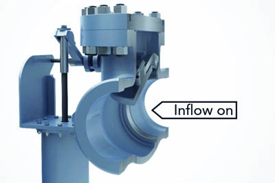
Rearming the actuator
Once the pneumatic actuator has provoked the valve closing, the Quick Closing system has to be rearmed. The QC system is designed to ensure that the rearming time of the actuator (compressing time of the spring) is less than 20 seconds.
The operation air pressure shall be in the range of 4-7 kg/cm2(g)
The piston travel shall be long enough to ensure the valve can be fully open and fully closed.
Testing without affecting the regular operation of the valve
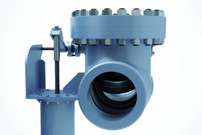
Testing device
The actuator is provided with a manually or remotely controlled “testing” solenoid valve to test periodically the right functioning pneumatic Quick Closing system. This operation permits to be sure that the main valve is always ready to operate in quick mode. It is especially recommended to be used after long periods of time in which the valve has constantly been in open condition due to the normal operation of the turbine.
VALVE WORKING AS FREE-SWINGING

During normal operation of the valve, Babcock ́s QCNRV shall work as a normal swing check valve of free movement. Babcock utilizes its streamlined own design to get a minimum pressure loss.
The movement of the disc shall be totally free due to the gravity and his own weight, to get the complete closing position at the first slight reverse flow or when no flow is in the line. Therefore, the valve functioning shall permit fluids to flow in only one direction.
VALVE WORKING AS QUICK CLOSING

The QCNRV are usually supplied with a pneumatic actuator to assist the disc to get a very quick closing. Alternatively, a hydraulic or other type of actuation is available upon request.
When a turbine trip occurs, the valve must close in an extremely short period of time for the maximum protection of the turbines preventing the backflow.
The best method for isolating and testing of piping sections.
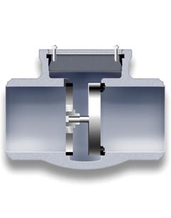
The Hydrotest valve (also named Reheater Isolating Device), is designed to provide an easy, effective and time saving way to carry out the piping hydrostatic test by isolating the re-heaters.
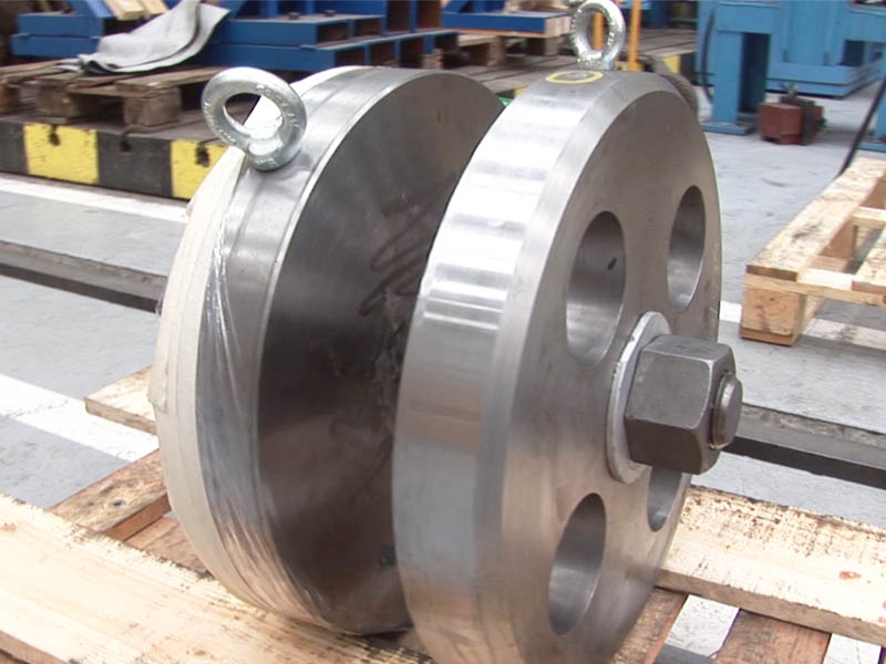
The valve has an Isolating Disc Assembly which will be only used during hydrostatic test of reheaters and shall be removed after successful completion of the tests. The isolation disc is used to isolate the pressurized side from the non-pressurized side.
Once the hydrostatic tests have finished, the isolating device is removed from the valve, permitting the free flowing of the fluid. The hydrotest valve body is permanently welded to the pipelines on both sides becoming an integral part of the piping without any obstruction inside.
Babcock will provide along with the valves all the necessary documentation for the storage, handling and installation of the hydrotest valves, as well as for the right assembly and disassembly of the internal isolating device.
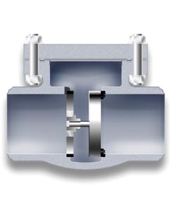
Code 44
Type: Hydrotest Check / Reheater Isolating Device
Cover: Bolted
Sizes: 2″- 48″
ANSI Class: 150-900
Code 08
Type: Hydrotest Check / Reheater Isolating Device
Cover: Pressure Seal
Sizes: 2″- 48″
ANSI Class: 600-4500
The most effective way of steam piping cleaning.
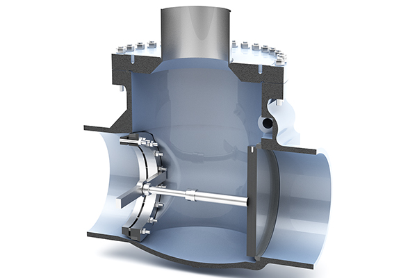
The so-called blowing device is an effective method for chemical cleaning of steam pipelines.
A check valve installed in the piping is used to carry out this cleaning procedure by means of removing its internals and installing the temporary device inside. Valve cover is also replaced by a special connection for steam blowing.
It is normally used when system is not working properly to remove the debris in the superheater, reheater and the steam pipeline connecting with the turbine.
Once cleaning process is completed the blowing device is removed to leave the valve working again as a check valve.
BELLOWS SEAL
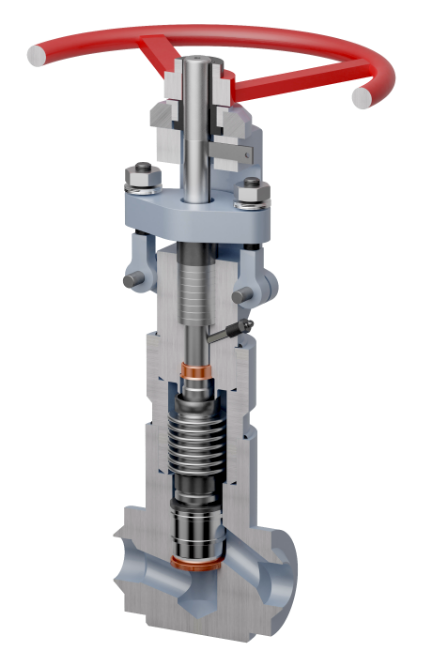
Bellows seal valves incorporates a bellows assembly welded to the bonnet and to the stem, so when the valve is being operated, bellows gets expanded or compressed, eliminating any risk of leakage to atmosphere that could happen to conventional valves, resulting ideal for uses on toxic of flammable piping systems in chemical plants and several applications on safety areas of nuclear plants.
In Babcock Valves, we use a high-strength multi-ply bellows designed to withstand high pressures and temperatures and to increase the fatigue strength. The bellows is generally supplied in SS321 material although other materials are available upon request.
Our bellows seal valves guarantee at least 10.000 failure-free cycles with zero leakage through the bottom of the bonnet and packing rings to achieve a long life service.
We manufacture gate and globe bellows seal valves in sizes from 1/2″ to 24″ and ASME class 150 to 2500.
CONTINUOUS BLOW DOWN
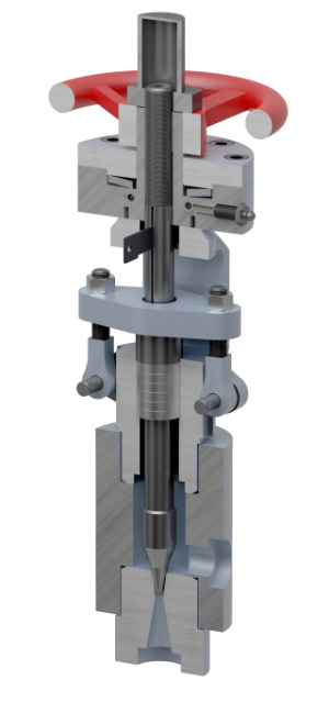
CBD (Continuous Blowdown) valve is designed to operate in open position for constant release of suspended salts from the highest solids concentration in the steam boiler drum through a blowdown tap outlet, keeping the TDS (total dissolved solids) at the right concentration limits.
CBD is a manual operated angle type and venturi effect valve incorporating a stem and needle disc made out of one piece, providing a strong and reliable product capable to withstand severe service conditions.
INTERMITTENT BLOW DOWN
IBD (Intermittent Blowdown) valve function is the removal of dissolved salts, mud and other solids located at the bottom of the steam boiler drum. The frequency of valve operation will depend on the need of boiler’s clean-up which can vary in each particular case.
IBD is a motor operated angle type valve with a stem and elongated needle disc made out of one piece, specially designed to work in several steps to minimize wear and to get an effective flushing of the sludge from the bottom of the steam drum.

BABCOCK VALVES S.A.
ADDRESS
P.E. Abra Industrial, Parcela 1.5.6 – 48530 Ortuella (Bizkaia) Spain
TELEPHONE
(+34) 944 536 423
FAX
(+34) 944 535 739
Inquiry form
You can send us any question of your interest.
We will get back to you as soon as possible.
Legal disclosures
Cookies policy
Privacy statement

