Gate valves: product range
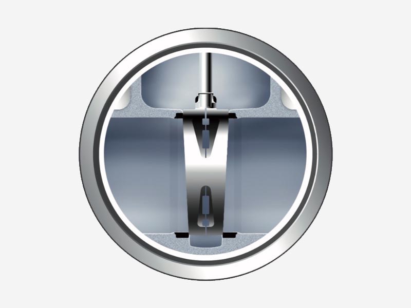
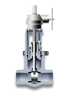
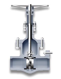
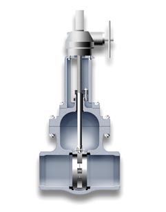
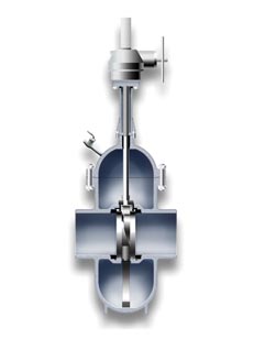
Wedge Gate Valves
Wedge gate valves are commonly supplied with solid wedge up to 2” size and with flexible wedge for larger sizes. The latter design consists of two independent and flexible wedge halves, that allow a relative movement to accommodate changes in the body seat angles.
The result is a valve with a high pressure sealing performance, with optimum results at low differential pressures, meeting industrial valve requirements, moved toward larger sizes and higher pressures and temperatures.
Design: ASME B16.34, API 600 for cast valves and API 602 for small size forged valves
Code 22
Type: Wedge Gate
Bonnet: Bolted
Sizes: 1/2″ – 72″
ANSI Class: 150-2500
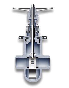
Code 25
Type: Wedge Gate
Bonnet: Pressure Seal
Sizes: 2″ – 48″
ANSI Class: 600-4500
Code 84
Type: Wedge Gate Cryogenic
Bonnet: Bolted
Sizes: 2″ – 48″
ANSI Class: 150-900
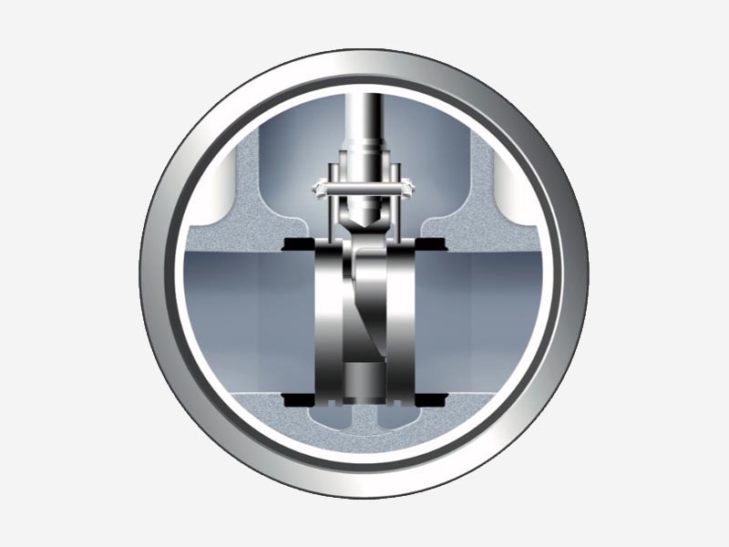
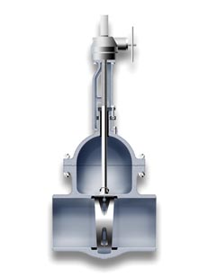
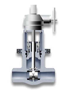
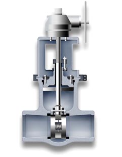
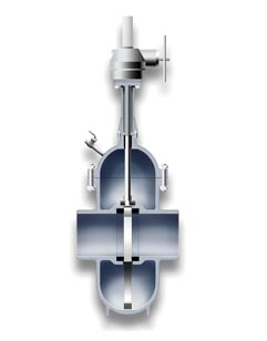
Double Disc Gate Valves
The so called double disc valve incorporates a double disc, double wedge and double seat system, which makes this design unique, being designed to assure a reliable operation under the most severe service conditions.
The two independent trunnion mounted discs which permit each disc to rotate a few degrees during closing. This rotating feature allows the discs to seat in a different position on each closing stroke which provides even wear and prevents small imperfections from growing into major leaks.
Design: ASME B16.34, API 600, BS 1414
Code 82
Type: Double Disc
Bonnet: Bolted
Sizes: 2″ – 72″
ANSI Class: 150-900
Code 85
Type: Double Disc
Bonnet: Pressure Seal
Sizes: 2″ – 48″
ANSI Class: 600-4500
Code 83
Type: Double Disc Cryogenic
Bonnet: Bolted
Sizes: 2″ – 48″
ANSI Class: 150-900
TECHNICAL ADVANTAGES OF THE DOUBLE DISC WEDGE ASSEMBLY

Reliable operation
The double disc gate valve has been designed to assure reliable operation under the most severe service condi- tions. Due to the special configuration and geometry of the upper wedge inclined face, any possibility of locking the disc in closed position is eliminated, even when closed quickly or subjected to severe thermal transients.
Easy maintenance
The four piece double disc wedge assembly can neither be incorrectly assembled nor become disengaged while in service. No special fitting at site is required for maintenance. The repair of minor seat or disc damage is greatly simplified because the seats and discs can be lapped independently of each other. Disassembly and maintenance can be accomplished without special tools or elaborate rigging.
Low pressure sealing
The wedge assembly is designed to impart sufficient thrust to each disc to maintain low pressure sealing. As the differential pressure across the disc increases, the seating load also increases, thus providing a tight seal throughout the entire range of operating differential pressures. Since the discs are independent of each other and the design is symmetrical, positive sealing can be maintained in either direction.
Uniform seat wear
The incorporation of a unique revolving disc feature assures maximum seat life. The two independent discs, during each closing stroke and immediately prior to the disc seating, rotate a few degrees in the plane of the seats. This rotating action forces the disc to seat in a different position on each stroke, equalizing wear on the seats and the discs. This movement of the discs creates a lapping effect whenever the valve is operated, removing particles from the sealing surfaces before they can become wedged between the seats and the disc and cause damage.
Uniform distribution of sealing pressure
The tight seal is guaranteed even when the valve seats have become out of parallel due to body distortion, due to the uniform distribution of the sealing pressures allowed by the exclusive wedge design.
Uniform distribution of sealing pressure
Babcock’s double disc wedge system permits rapid closure without seat distortion. Internal moving parts decelerate independently of each other with the result that inertial forces are dissipated in a series of impacts over a period of time. The largest force is transmitted directly to the bottom of the valve body on a non-sealing surface. Forces transmi- tted directly to the seats a small percentage of the seats are a small per centage of the total inertial forces. This is a distinct advantage over valve designs in which the total inertial force is absorbed directly by the seating surface.
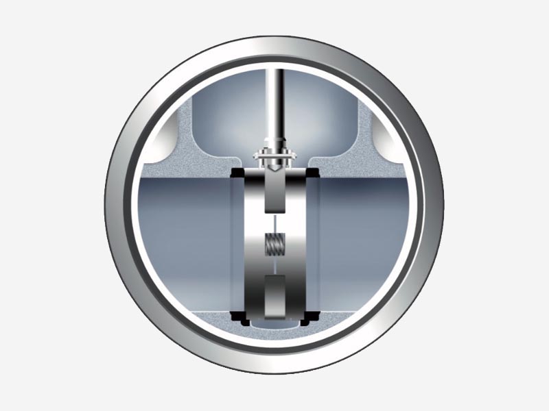
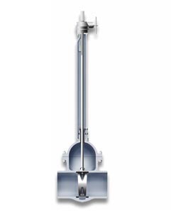
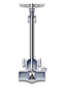
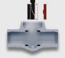
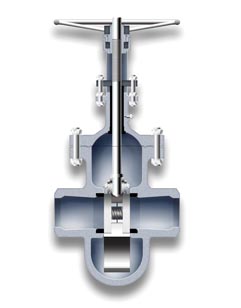
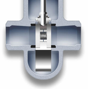
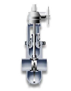
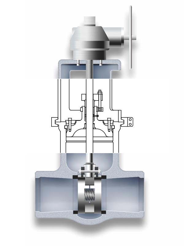
Parallel Slide Gate Valves
An alternative to double disc valves, having two discs but only one wedge instead of two. The discs are in permanent contact with the seat rings, getting a tight seal due to the horizontal inconel spring located in between and without the wedging system help.
Design: ASME B16.34, API 600, BS 1414
Code 86
Type: Parallel Slide (with follower eye)
Bonnet: Pressure Seal
Sizes: 2″ – 48″
ANSI Class: 600-4500
Code 88
Type: Parallel Slide (with follower eye)
Bonnet: Bolted
Sizes: 2″ – 48″
ANSI Class: 150-900
Code 87
Type: Parallel Slide
Bonnet: Bolted
Sizes: 2″ – 48″
ANSI Class: 150-900
Code 89
Type: Parallel Slide
Bonnet: Pressure Seal
Sizes: 2″ – 48″
ANSI Class: 600-4500
PARALLEL SLIDE DESIGN MAIN FEATURES
CODE 86-88
Follower eye for very laminar flow is available on request. It avoids any turbulences and minimizes the pressure drop.
-
Two discs and just one wedge design gate valve.
-
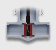
Parallel slide gate valve provides a smooth flow path between seats.
-
This design of gate valve is commonly used for clean fluids and steam applications.
-
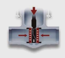
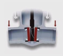
System pressure is used to provide isolation. The closing is only made over one of the seats. The higher pressure in the system, the better closing tightness.
-
The discs have a certain movement to assure its right alignment with the seats contact faces when closing (seal is established on outlet seat face only), avoiding any mechanical stress.
-
The inconel spring located between both discs, provides initial seating force. Once the discs are in the right position, no additional torque is necessary to achieve a positive seal.
-
Torque requirement is lower than other gate valves as wedge type because needs lower operative forces.
-
The wiping action of the discs over seats while the valve is operating removes debris and prevents premature wear of the components. A long life service is guaranteed by means of hardening seats and discs with an extra hard material as Stellite 6, Tribaloy or others.
-
Parallel slide system avoids jamming related to cooling down of the pipeline.
-
A wide range of construction materials, actuation systems and accessories are available for each case.
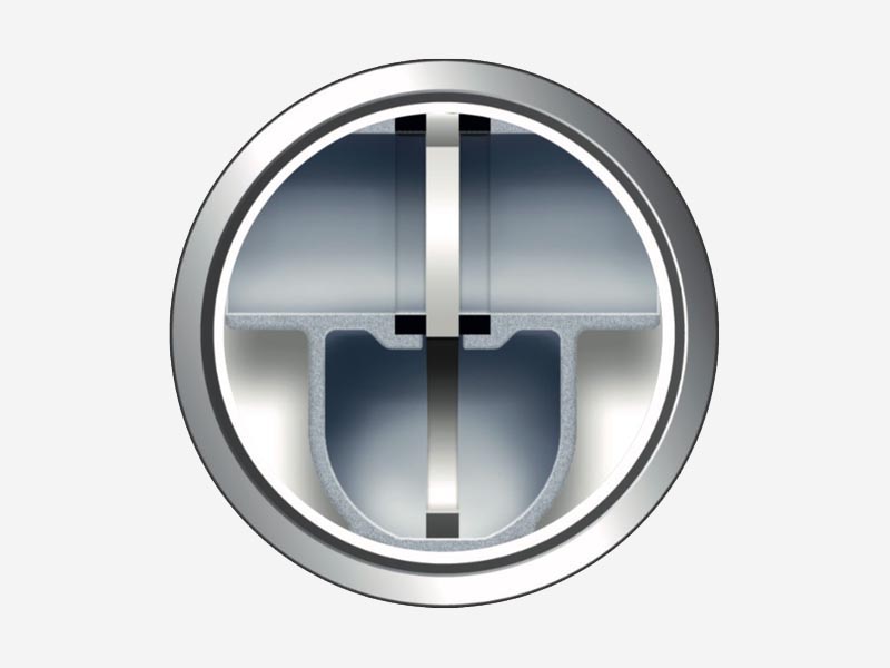
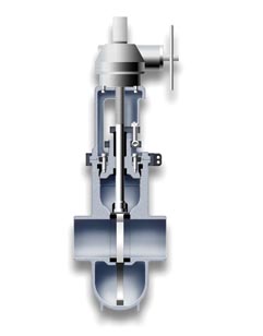
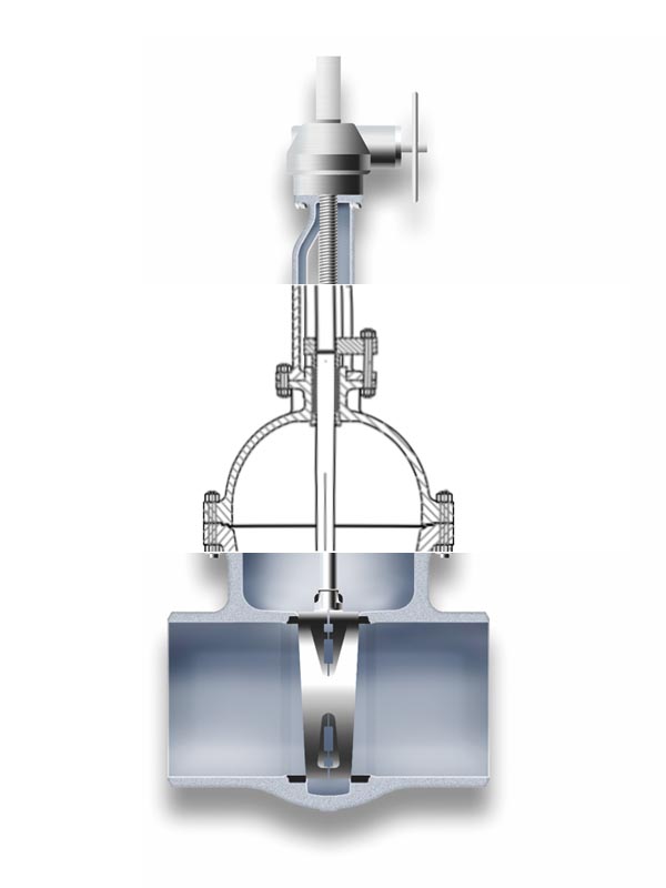
Through Conduit Gate Valves
Through conduit is a type of gate valve designed as per API 6D for transmission pipelines service. The valve is full port design, with same inside diameter than the upstream / downstream pipe, to allow the cleaning equipment to travel through.
The double block and bleed design permits a complete flushing, and drainage and venting of the valve cavity through the drain valve located at the bottom of the body.
Design: ASME B16.34, API 6D
Code 10
Type: Trough conduit
Bonnet: Pressure Seal
Sizes: 2″ – 48″
ANSI Class: 600-4500
Code 00
Type: Trough conduit
Bonnet: Bolted
Sizes: 2″ – 60″
ANSI Class: 150-900
Code 83
Type: Parallel Expanding
Bonnet: Pressure Seal
Sizes: 2″ – 48″
ANSI Class: 600-4500
Code 81
Type: Parallel Expanding
Bonnet: Bolted
Sizes: 2″ – 60″
ANSI Class: 150-900
Types of Bonnet
The most common connection between valve body and bonnet for ASME ratings up to 600.
Under demand, it can be also used for high pressure applications up to class 2500.
The Babcock’s strong designs and a precision machining of bodies and bonnets shall guarantee the best performances of the valves during operation.
The right sealing between body and bonnet is made by designing a more than sufficient type and number of bolts, and selecting the best gasket for each service.
There are different joint / gasket designs for each applicable ASME rating. A flat oval gasket is normally used for low pressure (class 150) and a spiral wound gasket for intermediate pressures (class 300) and high pressure (class 600). Other type of joints as corrugated or ring type are also available under demand.
NOTE:
For Class 900 and superior, the Bolted Bonnet gasket used is RTJ.
STANDARD BOLTED BONNET GASKETS
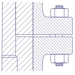
Class 150
Detail for
FLAT GASKET
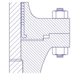
Class 300
Detail for
SPIRAL WOUND GASKET
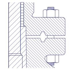
Class 600
Detail for
RTJ GASKET
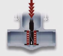
Pressure seal bonnets allow high pressure service, typically in excess of 15 Mps (2250 psi).
The main feature about the pressure seal bonnet is that the body-bonnet joints seals improves as the internal pressure in the valve increases, compa- red to other constructions where the increase in internal pressure tends to create leaks in the body-bonnet joint.
The basic operation of this kind of valve, where the seal is achieved from the pressure exerted by the fluid flowing trough the valve, is as follows:
Internal pressure forces the bonnet upwards against the gasket, creating forces in the contact areas between the gasket and the bonnet and between the gasket and the body.
Leaks most commonly arise at the contact surface between the gasket and the body. The area where the body is in contact with the joint is covered by stainless steel, improving surface’s quality and avoiding corrosion issues.
Gaskets are carefully designed to produce a tight seal regardless of the line conditions, that can be easily dismantled for maintenance operations.
GENERAL DESCRIPTION
The basic operation of this kind of valve, where the seal is achieved from the pressure exerted by the fluid flowing through the valve, is as follows:
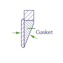
Fig. 1
Forces making the seal
Internal pressure forces the bonnet upwards against the gasket creating forces in the areas of contact between the gasket and the bonnet (disc shaped area). and between the gasket and the body (valve passage area). See (Fig. 1 ). The quality of the seal between the surfaces depends upon two basic considerations, these being the surface quality of the areas in contact, and the degree of force (load per unit area) which holds them together.
It is easier to achieve the seal from the two gasket surfaces where a seal is made (gasket-bonnet and gasket-body) in the gasket bonnet contact area, in comparison to the larger component of the force exerted by the pressure inside, and it is more than sufficient to provide a tight seal.
Leaks most commonly arise at the contact surface between the gasket and the body. The .area where the body is in contact with the joint (Fig. 2) is covered with stainless steel, and this improves surface quality and avoids corrosion problems. The force actuating between the contact joint body surfaces is the horizontal component of force perpendicular to the contact surfaces between the bevelled surfaces of the joint and bonnet. The efficiency of the seal between the gasket and body is determined basically by the gasket angle, which in turn determines the horizontal force component that will act upon them. The smaller the gasket angle, the greater the horizontal component is, and hence, the harper the angle on the bevelled surface, the greater the horizontal component, and the better the seal.
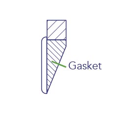
Fig 2
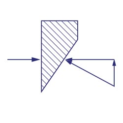
Fig. 3
Angle 25º
A gasket designed with a 25° angle (Fig. 3) will turn into radial force, a greater component of the force exerted by the pressure from the line on the bonnet, than a gasket designed with an angle of 30° 45° (Fig.4). Moreover, in order to achieve large unitary loads, the surface upon which the force is exerted may be reduced, with checks being performed to ensure that the surface is sufficient to support the load without cracking.
When a pressure seal joint is required to seal over a large range of pressures, there may be difficulties. A gasket which is sufficiently small so as to seal under a pressure of 500 psi. may not support 2.500 psi.
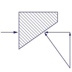
Fig. 4
Angle 45º
A way to overcome this problem is to design the gasket bonnet contact surfaces to have a difference of one degree between them (Fig. 5).
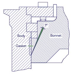
Fig. 5
Before the gasket is tightened, only its edge is in contact with the bonnet (Fig. 6).
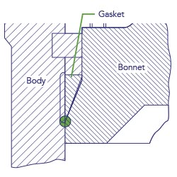
Fig. 6
Under pressure, one part of the gasket will deform and enter into contact with the bonnet (Fig. 7).
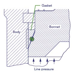
Fig. 7
A careful design of the gasket pressure seal angle will prevent those more serious difficulties found with large angle gaskets (30°-45°). With a narrow gasket angle (25°), a tight seal can be achieved by applying little pressure, and once the seal has been made, it will stay tight regardless of line conditions. Certain tests performed with narrower gaskets (15°-20°), showed that the seal became so tight that it was impossible to remove the gasket. A gasket of approximately 25° is found to produce a seal that can be easily dismantled.
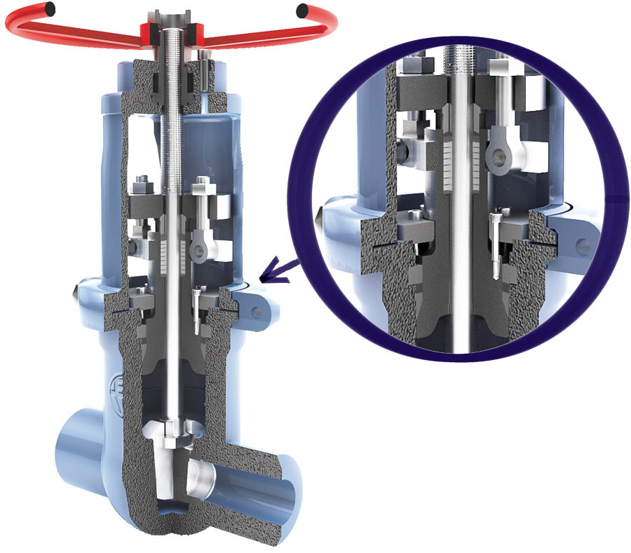
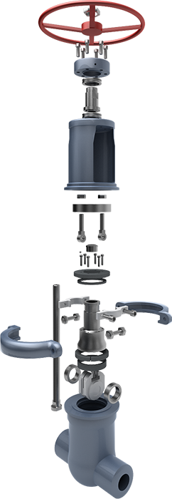
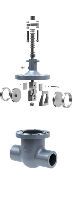
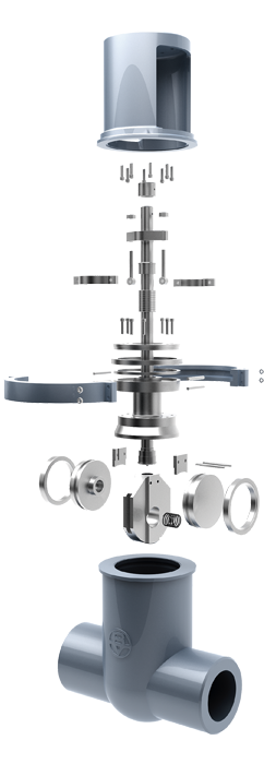
BODY
Available both in cast and forged steel, it has been designed to meet all the requirements of ASME, API and British Standards.
The body-bonnet connection is made by a pressure seal gasket. Its pre-stress condition is achieved by means of bolts screwed to the bonnet flange.
Ends are normally butwelding although they can be also flanged on request.
All bodies are provided with integrally cast bosses, located and sized in accordance with ASME B16.34, which allow the provision of drain and by-pass connections, supplied on request.
BONNET
Usually constructed in the same materials as the body, being designed so that the wall thickness always exceeds the require- ment of API 600.
A back seat bush (13.) is fitted inside the bonnet lower cavity, to provide a closure when de valve is fully opened. This permits the valve to be repacked while in service.
The bonnet has a deep stuffing box in which packing rings are placed.
Stuffing box is designed with sufficient space to allow lantern ring to be fitted.
YOKE
Separate rigid yoke provided to withstand the thrust of the actuator. Large windows allow easy access and ventilation of the packing area. The yoke is connected to the body by a two piece clamping ring (193.) an four clamp bolts. This connection is very solid and enables easy maintenance at site.
The upper part of the yoke is suitably machined to house the yoke sleeve (11.).
The yoke is usually made of cast carbon steel regardless the type of body material, unless otherwise required by the client.
STEM
Constructed in stainless steel, machined from solid bar stock. The single piece stem in connected to the wedge by a tee connection.
A conical shoulder is also provided to ensure effective and tight seal backseat which allows the stuffing box to be replaced with the valve in service. The stem dimensions conform to API 600. Connection stem-wedge also meets the requirements of API 600. Pull test has been carried out to verify the design. Special care is taken in the machining of the stem, including the final polishing of the travelling area (contact with the stuffing box). This allows a low-friction surface and a superior corrosion resistance.
GLAND BOLTS & NUTS
The gland studs are of the eyebolt type, which can be swing outwards for ease of gland repacking.
GLAND BUSHING & GLAND FLANGE
They are supplied in two separate self aligning pieces, to ensure uniform pressure is effected during tightening of the packing.
The upper part of the gland, which comes in contact with the gland flange, is spherical in shape.
The gland flange is made of carbon steel but, upon request, other materials can be supplied.
SEAT RINGS
They are supplied in forged stainless steel, hardfaced with Stellite-6 (2 mm of minimum thickness). Seat rings are renewable, normally welded to the body.
Sealing contact surfaces, are lapped for a perfect tight seal. Controlled hardness differentials are maintained between the wedge discs and the seat rings, as requi- red by API 600 Std.
WEDGE
The wedge is normally constructed in forged stainless steel for diameters up to 3”, and in cast steel for larger sizes.
Wedge is commonly flexible, though it can be also solid. Guides are carefully machi- ned for a smooth sliding in the body cast-in guides.
Contact faces are overlayed with stellite-6 (2 mm of. minimum. thickness).
YOKE CLAMP
The connection between body and yoke is created by means of a bipartite clamping ring. The internal connection between the clamp, body and yoke is conical, assuring a perfect tightening.
YOKE SLEEVE
Designed to permit removal from the bonnet or yoke while the valve is in service.
The yoke bushing assembly is mounted in ball bearings. It is normally made of cast aluminium bronze, having high resistance to wear and high melting point. Other materials such as Ni-resist can be supplied on request.
BACK SEAT
The back seat can be supplied as a threaded stainless steel bush, welded to the bonnet or of integral type. It can be hardfaced with Stellite-6 or orther materials as required.
This seat allows the valve to be repacked under pressure.
HANDWHEEL
The handwheel can be supplied either in cast construction of fabricated from steel tube.
The handwheel is designed to allow easy operation of the valve. Other types of control are available and, in some cases, are indispensable for a good operation, for instance: Chain wheel, gear operator, hammer handwheel, geared hammer handwheel, electric actuator, electro-hydraulic actuator or pneumatic actuator.
PRESSURE SEAL GASKET
The pressure seal gaskets are usually supplied of compressed graphite, bordered on the upper and lower edges with braided filaments of graphite and Inconel.
Gaskets can also be made in stainless steel.
PACKING
Packing is made of an adequate number of preformed rings.
For general applicatios high grade graphite material is supplied, using compressed rings in the center and braided anti-extrusion rings on top and bottom. Graphite is selec- ted of an approved quality.
Other types of packing are also available for particular services.
SPACER RING
Made of a single piece coverting the upper part of the pressure seal gasket. It is normlly manufactured in the same material as the body.
GASKET RETAINER
It is made normally of the same material as the body, and constructed in four pieces, called segments. The segments are sized to minimize the gap among them.
The segmental ring supports all the forces transmitted from the bonnet through the spacer ring. It is calculated to withstand all the force without cracking.
BONNET RETAINER
Designed sufficiently resistant to withstand the forces transmitted by the bonnet screws (111).
The bonnet retainer is normally made of the same material as the body, but it can be constructed in any other material on request. It is machined to match exactly with the body, what guarantees a perfect alignment of the unit.
BABCOCK VALVES S.A.
ADDRESS
P.E. Abra Industrial, Parcela 1.5.6 – 48530 Ortuella (Bizkaia) Spain
TELEPHONE
(+34) 944 536 423
FAX
(+34) 944 535 739
Inquiry form
You can send us any question of your interest.
We will get back to you as soon as possible.
Legal disclosures
Cookies policy
Privacy statement