Stop-Check valves: product range
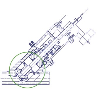
Stop-check valves are commonly used for a safety operation associated to boilers
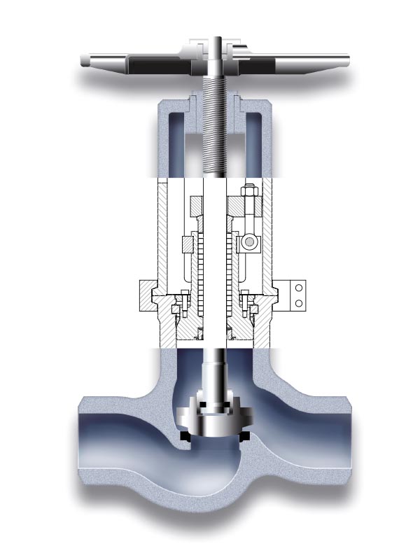
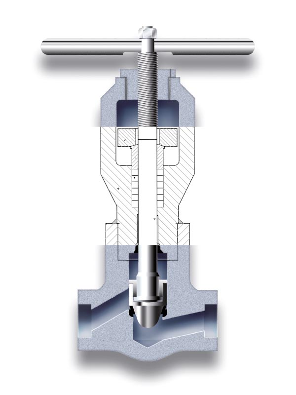
This kind of valve is normally used in power plants for safe operation of a boiler. It combines the performances of a globe and a non return valve and can be supplied in straight, Y-type, angle or Y-angle designs.
It is a globe valve with its stem disconnected from the disc. Therefore, when it is in open position, the valve works as a lift check valve with freely movement disc preventing backflow automatically; and when it is close, it will also provide a tight seal. Intermediate stem positions are available limiting the disc travel and controlling the flow rate.
The stop-check valve can then be used for isolation, regulation and prevention of backflow.
STOP-CHECK PERFORMANCES
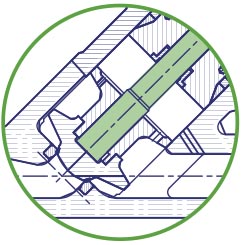
CLOSE POSITION
Fluid cannot pass through the valve.

OPEN POSITION
The valve works as a check valve.
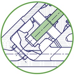
INTERMEDIATE POSITION
Fluid can circulate although restricted by the intermediate position of the stem. The valve works as a check valve but only to a certain point.
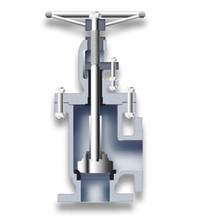
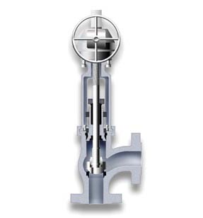
Code 97
Type: Angle Stop-Check
Bonnet: Bolted
Sizes: 2″- 24″
ANSI Class: 150-900
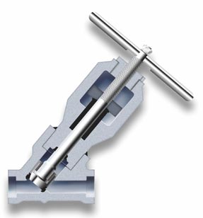
Code 94
Type: Angle Stop-Check
Bonnet: Pressure Seal
Sizes: 2″- 24″
ANSI Class: 600-900
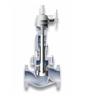
Code 76
Type: Globe Stop-Check
Bonnet: Threaded & Welded
Sizes: 1/2″- 12″
ANSI Class: 150-4500
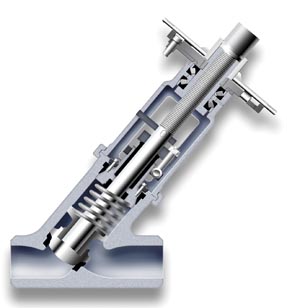
Code 62
Type: Globe Stop-Check
Bonnet: Bolted
Sizes: 1/2″- 24″
ANSI Class: 150-2500
Code 73
Type: Y- Globe Stop-Check
Bonnet: Pressure Seal
Sizes: 2″- 24″
ANSI Class: 600-4500
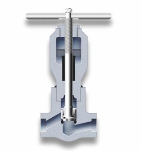
Code 61
Type: Globe Stop-Check
Bonnet: Threaded & Welded
Sizes: 1/2″- 12″
ANSI Class: 150-4500
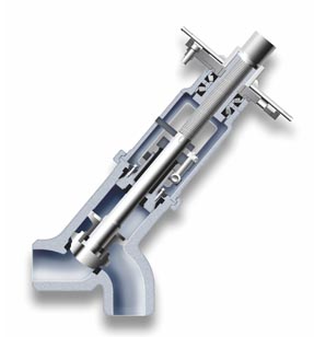
Code 90
Type: Y-Angle Stop-Check
Bonnet: Pressure Seal
Sizes: 2″- 48″
ANSI Class: 600-4500
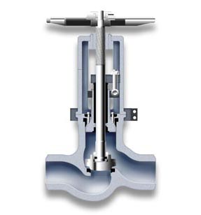
Code 65
Type: Stop-Check
Bonnet: Pressure Seal
Sizes: 2″- 24″
ANSI Class: 600-4500
Types of Bonnet
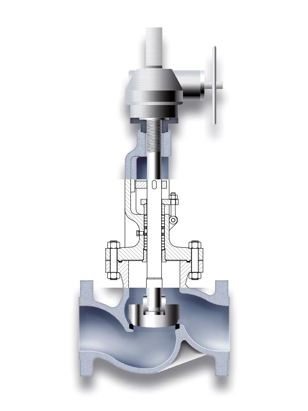
The most common connection between valve body and bonnet for ASME ratings up to 600.
Under demand, it can be also used for high pressure applications up to class 2500.
The Babcock’s strong designs and a precision machining of bodies and bonnets shall guarantee the best performances of the valves during operation.
The right sealing between body and bonnet is made by designing a more than sufficient type and number of bolts, and selecting the best gasket for each service.
There are different joint / gasket designs for each applicable ASME rating. A flat oval gasket is normally used for low pressure (class 150) and a spiral wound gasket for intermediate pressures (class 300) and high pressure (class 600). Other type of joints as corrugated or ring type are also available under demand.
NOTE:
For Class 900 and superior, the Bolted Bonnet gasket used is RTJ.
STANDARD BOLTED BONNET GASKETS
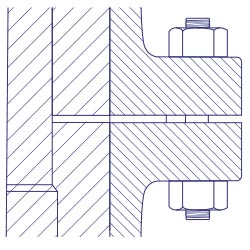
Class 150
Detail for
FLAT GASKET
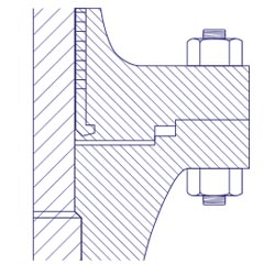
Class 300
Detail for
FLAT GASKET
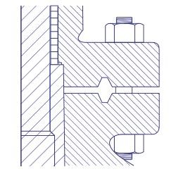
Class 600
Detail for
FLAT GASKET
Pressure seal bonnets allow high pressure service, typically in excess of 15 Mps (2250 psi).
The main feature about the pressure seal bonnet is that the body-bonnet joints seals improves as the internal pressure in the valve increases, compa- red to other constructions where the increase in internal pressure tends to create leaks in the body-bonnet joint.
The basic operation of this kind of valve, where the seal is achieved from the pressure exerted by the fluid flowing trough the valve, is as follows:
- Internal pressure forces the bonnet upwards against the gasket, creating forces in the contact areas between the gasket and the bonnet and between the gasket and the body.
- Leaks most commonly arise at the contact surface between the gasket and the body. The area where the body is in contact with the joint is covered by stainless steel, improving surface’s quality and avoiding corrosion issues.
- Gaskets are carefully designed to produce a tight seal regardless of the line conditions, that can be easily dismantled for maintenance operations.
GENERAL DESCRIPTION
The basic operation of stop-check valves, where the seal is achieved from the pressure exerted by the fluid flowing through the valve, is as follows:

Fig. 1
Forces making the seal
Internal pressure forces the bonnet upwards against the gasket creating forces in the areas of contact between the gasket and the bonnet (disc shaped area). and between the gasket and the body (valve passage area). See (Fig. 1 ). The quality of the seal between the surfaces depends upon two basic considerations, these being the surface quality of the areas in contact, and the degree of force (load per unit area) which holds them together.
It is easier to achieve the seal from the two gasket surfaces where a seal is made (gasket-bonnet and gasket-body) in the gasket bonnet contact area, in comparison to the larger component of the force exerted by the pressure inside, and it is more than sufficient to provide a tight seal.
Leaks most commonly arise at the contact surface between the gasket and the body. The area where the body is in contact with the joint (Fig. 2) is covered with stainless steel, and this improves surface quality and avoids corrosion problems. The force actuating between the contact joint body surfaces is the horizontal component of force perpendicular to the contact surfaces between the bevelled surfaces of the joint and bonnet.
The efficiency of the seal between the gasket and body is determined basically by the gasket angle, which in turn determines the horizontal force component that will act upon them. The smaller the gasket angle, the greater the horizontal component is, and hence, the harper the angle on the bevelled surface, the greater the horizontal component, and the better the seal.

Fig 2

Fig. 3
Angle 25º
A gasket designed with a 25° angle (Fig. 3) will turn into radial force, a greater component of the force exerted by the pressure from the line on the bonnet, than a gasket designed with an angle of 30° 45° (Fig.4). Moreover, in order to achieve large unitary loads, the surface upon which the force is exerted may be reduced, with checks being performed to ensure that the surface is sufficient to support the load without cracking.
When a pressure seal joint is required to seal over a large range of pressures, there may be difficulties. A gasket which is sufficiently small so as to seal under a pressure of 500 psi. may not support 2.500 psi.

Fig. 4
Angle 45º
A way to overcome this problem is to design the gasket bonnet contact surfaces to have a difference of one degree between them (Fig. 5).

Fig. 5
Before the gasket is tightened, only its edge is in contact with the bonnet (Fig. 6).

Fig. 6
Under pressure, one part of the gasket will deform and enter into contact with the bonnet (Fig. 7).

Fig. 7
A careful design of the gasket pressure seal angle will prevent those more serious difficulties found with large angle gaskets (30°-45°). With a narrow gasket angle (25°), a tight seal can be achieved by applying little pressure, and once the seal has been made, it will stay tight regardless of line conditions. Certain tests performed with narrower gaskets (15°-20°), showed that the seal became so tight that it was impossible to remove the gasket. A gasket of approximately 25° is found to produce a seal that can be easily dismantled.
The double sealed design.
Stop-check valves can be supplied with a threaded and welded bonnet. Unlike the bolted bonnet and pressure seal body-bonnet closure systems, the threaded & welded system consists of a double-sealed design, first by threading the bonnet-yoke to the body, and second by sealing it by means of a welding seam.
The necessary non destructive tests are carried out to ensure a perfect sealing.
Under demand, a sealing gasket can also be placed between body and bonnet.
The threaded & welded design is primarily used on small size forged valves up to 2″, and for high pressure ratings, from ASME class 900 to 4500.
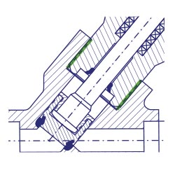
Threaded
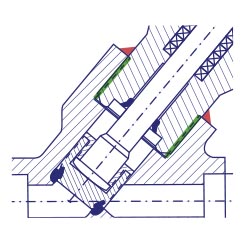
Welded
BABCOCK VALVES S.A.
ADDRESS
P.E. Abra Industrial, Parcela 1.5.6 – 48530 Ortuella (Bizkaia) Spain
TELEPHONE
(+34) 944 536 423
FAX
(+34) 944 535 739
Inquiry form
You can send us any question of your interest.
We will get back to you as soon as possible.
Legal disclosures
Cookies policy
Privacy statement
